Rod Breakdown vs Intermediate vs Fine: Comparing Wire Drawing Machine Stages for Copper Lines
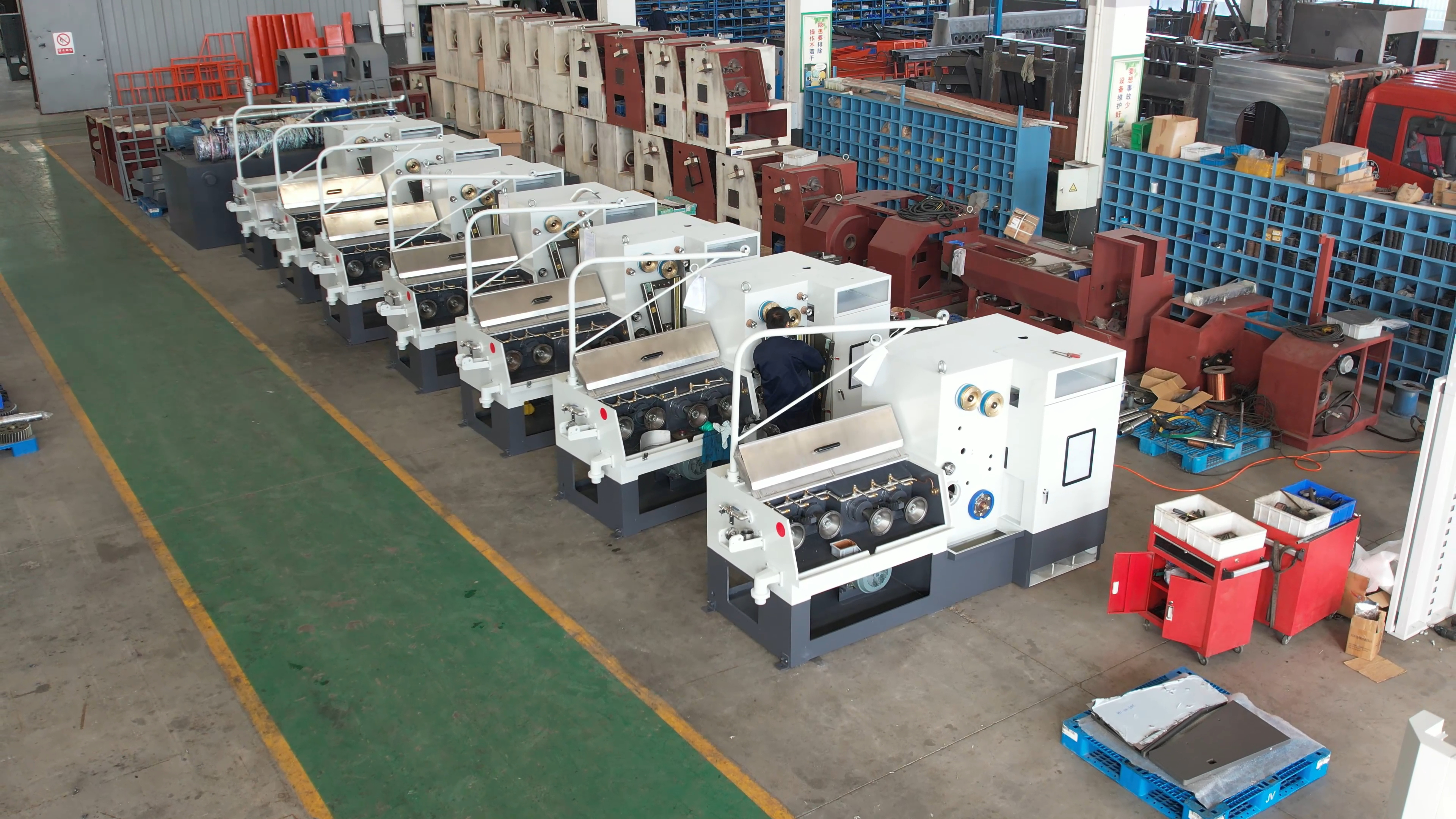
Cover: fine drawing stage machine in the assembly workshop of Jiangsu Listrong Mechanical & Electrical Co., Ltd., Dongtai, Jiangsu, China.
Short answer: copper wire drawing stages are defined by diameter windows, not by machine footprint. Rod breakdown runs copper rod from a maximum inlet of Φ8 mm down to Φ1.2–4.0 mm on up to 13 dies (LHD450-13DT). Intermediate drawing runs Φ3.5–2.5 mm inlet down to Φ1.6–0.4 mm outlet on 17 dies (17DST). Fine drawing runs Φ1.0–1.6 mm inlet down to Φ0.15–0.6 mm outlet on 22 dies (22DTA). Because those windows overlap partially, the handoff diameter you set between machines decides whether a copper line needs two stages or three.
This guide is written for the evaluation stage of a purchase, when the machine category is already known and the open question is which stage, or which stage combination, matches the finished copper wire you actually sell. All machine specifications quoted below are the published machine data of Jiangsu Listrong Mechanical & Electrical Co., Ltd., a wire and cable equipment manufacturer founded in 2009 in Dongtai City, Jiangsu, China, operating a 15,000 m² factory with a 15-engineer R&D team and an annual output of 550 sets.
Why Stage Selection Is Where Copper Lines Go Wrong
A diameter-window mismatch, not machine quality, is the most common cause of an underperforming or over-specified copper drawing line. Four failure patterns repeat across projects.
- Inlet larger than the machine accepts. The 22DTA accepts Φ1.0–1.6 mm. Feeding Φ2.5 mm or Φ3.0 mm wire into a fine drawing machine sits outside its stated inlet range, and no amount of die adjustment changes the geometry.
- Outlet target below the machine's floor. The LHD450-13DT delivers Φ1.2–4.0 mm. If the finished enamel base wire is Φ0.4 mm or Φ0.15 mm, no setpoint inside that machine reaches it.
- Annealing placed at the wrong stage. All three stages carry annealing capability, but at very different electrical ratings: 60V × 6000A DC on the LHD450-13DT rod breakdown machine, an online annealing arrangement with a 7.5 kW annealing motor on the 17DST, and DC three-section annealing at 60V, 600A maximum, 36 kVA on the 22DTA. Duplicating annealing capacity that you never use is capital that produces no extra output.
- Hidden scope items that surface after the order. Dies on the 17DST and the 22DTA are customer self-provided and the die formats differ by stage: Φ30 mm × 15 mm T or Φ25 mm × 10 mm T on the intermediate machine, and Φ25 mm × 8–12 mm T on the fine machine. Utility and floor requirements also scale sharply — 800 kVA total main power, 40,440 kg gross weight and a 32,550 mm long unit for stage one, against 3,500 kg and a 3,500 × 1,600 × 1,700 mm footprint for stage three.
The practical cost of getting this wrong is not a single bad machine. It is a line where one stage is idle, one stage is overloaded outside its inlet or outlet range, and the buyer ends up ordering a third machine to cover a gap that a different handoff diameter would have closed.
Industry Background: Why Stage Decisions Are Being Revisited Now
The global wire drawing machine market was valued at USD 3.8 billion in 2025 and is expected to reach USD 6.1 billion by 2034, a CAGR of 5.47% across 2026–2034 (Dataintelo, Wire Drawing Machine Market Research Report 2034, April 2026). Electrification-driven demand — power cable conductors, communication and data cable conductors, and automotive wiring — is the demand profile most often associated with that growth, and it is also the profile that shifts product mix toward the thin end of the copper range, which is exactly where stage selection decides whether a line is economic.
For importers and procurement teams, these machines fall under HS code 8463.30.00, machine tools for working metal wire without removing material, as classified by the World Customs Organization and used in UN Comtrade trade statistics. That classification matters at the documentation stage: a multi-stage line is normally shipped as separate machine units with separate model designations, so the classification and conformity paperwork has to match each unit rather than the line as a whole.
The Three Copper Drawing Stages, Machine by Machine
Stage 1: Rod Breakdown — LHD450-13DT
Rod breakdown is the first step in cable production: it reduces coarse copper rod to standard medium or intermediate wire before any finer drawing, bunching or stranding. The LHD450-13DT is a rod breakdown machine with a maximum inlet diameter of Φ8 mm and an outlet diameter range of Φ1.2–4.0 mm. It runs a maximum of 13 dies with a reduction ratio of 1.368–1.20, where the 13 dies are adjustable and the last pass is adjustable; maximum drawing speed is 25 m/s.
Because this stage moves the largest cross-section, it carries the largest drive package: a 280 kW main drawing motor, a 75 kW final capstan motor, a double spooler driven by 2 × 30 kW motors in two sets, an 18.5 kW-6P drop coiler motor, and a total main power of 800 kVA. Inline annealing is rated at 60V × 6000A DC. Take-up bobbins are PND500 or PND630, the maximum payoff coil outside diameter is 2,000 mm, and traversing pitch is 6.5 mm. The capstan diameter of 450 mm is what gives the model its name and its working envelope. The unit measures 32,550 × 4,500 × 3,820 mm with a gross weight of 40,440 kg, so civil works, lifting capacity and cable routing should be confirmed before the order, not after.
Buyers evaluating this stage should treat annealing power as the decisive optional item: 60V × 6000A DC is the largest annealing package of the three stages and is normally justified only when the line feeds directly into heavy-duty downstream processes.
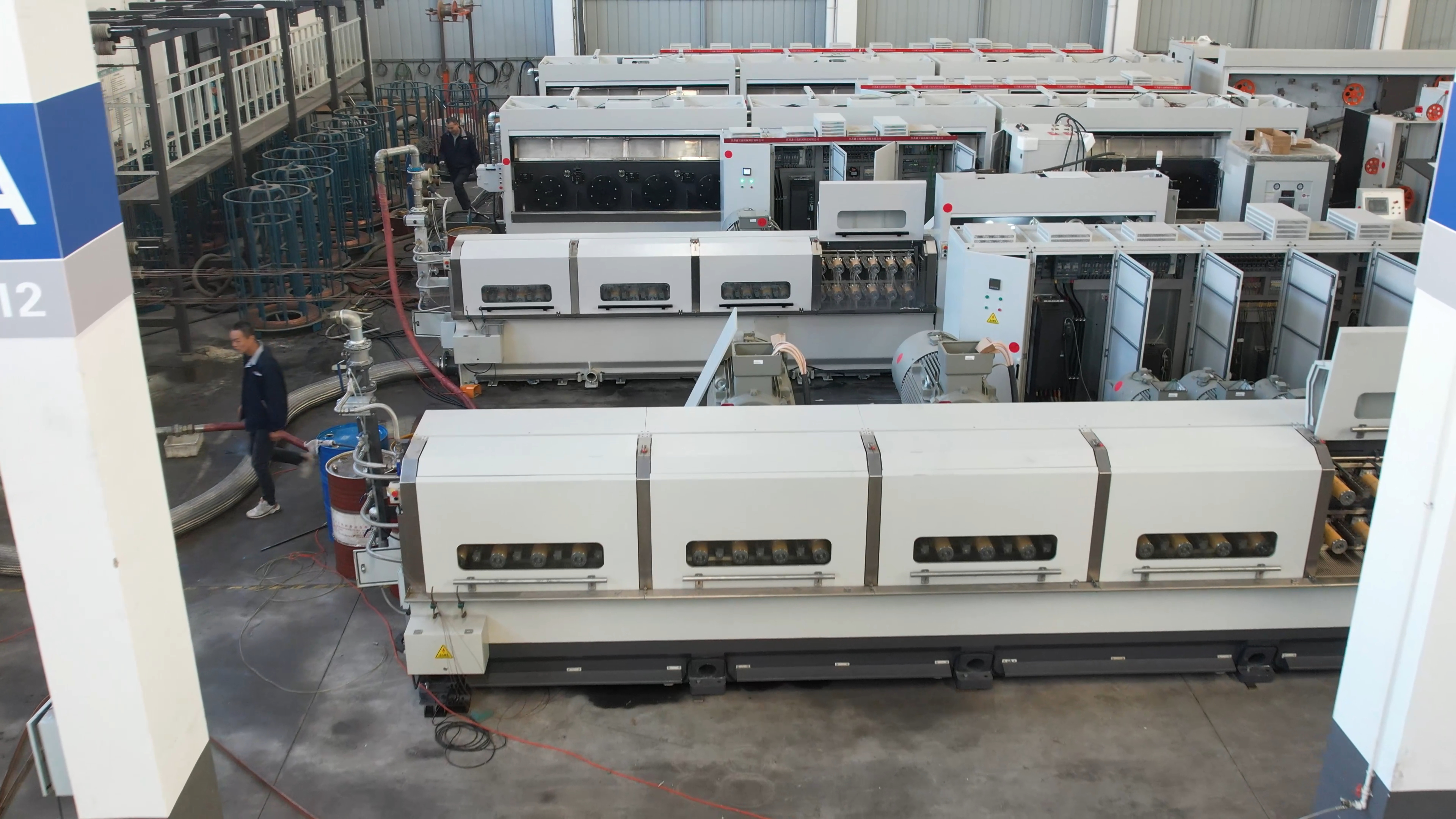
Assembly workshop: drawing machines prepared for copper and cable production lines.
Stage 2: Intermediate Drawing — 17DST
Intermediate drawing takes already-reduced rod and brings it into the range used by power cable conductors, communication cables, automotive wiring harnesses, electronic components and building wiring. The 17DST accepts Φ3.5–2.5 mm inlet and delivers Φ1.6–0.4 mm outlet, combining bare copper wire drawing with online annealing in a single pass-through.
It uses 17 dies, customer self-provided, in Φ30 mm × 15 mm T or Φ25 mm × 10 mm T format, with the last die in Φ25 mm × 10 mm T. Surface reduction is 20% from die No.1 to die No.16 and 15.5% on die No.17. Maximum mechanical speed is 1,800 m/min, falling to 1,500 m/min with annealing. Published reference speeds for this model are 1,000–1,500 m/min at 0.40–0.80 mm outlet and 1,300–600 m/min at 0.80–1.60 mm outlet, with wire elongation of 25% and 30% respectively. Driving power is a 55 kW main motor, a 7.5 kW annealing motor and a 15 kW spooling motor, with fully immersing lubrication at 100 litres per minute, a 90 W traversing motor with position-limited switch and a sliding safety door.
The speed table is the most useful procurement detail on this model. As the outlet diameter rises from 0.40 mm to 1.60 mm, line speed falls from the top of the range to the bottom of it, so throughput planning for an intermediate machine has to be done against the specific outlet diameter, not against the headline mechanical speed figure.
Stage 3: Fine Drawing — 22DTA
Fine drawing produces the diameters that go into enamel-coated wire for motor, transformer, compressor and generator windings, network and coaxial cable conductors, USB and data wires, and low-power drive or control coils. The 22DTA takes Φ1.0–1.6 mm inlet and delivers Φ0.15–0.6 mm outlet at a maximum drawing speed of 2,000 m/min.
It runs 22 dies, customer self-provided in Φ25 mm × 8–12 mm T format, where die No.1 is independent and dies No.2–21 are cast iron. Surface reduction is 15% from die No.1 to die No.21 and 8% on die No.22. Annealing is DC three-section at 60V, 600A maximum and 36 kVA. The drive package is smaller and the take-up lighter than the upstream stages: an 18.5 kW (25 HP) drive motor and a 2.2 kW (3 HP) spooling motor, both AC frequency-converter controlled; ceramic capstans in a four 10-tier arrangement plus one single-tier capstan for final drawing; spool outside diameter DIN200/250 with a 25 kg take-up capacity; 110 W synchronizing-motor traversing up to 270 mm wide; and a 10 KG-M magnetic brake. Spray lubrication runs at 40 litres per minute with independent lubrication lines to die No.1 and die No.22. The machine measures 3,500 × 1,600 × 1,700 mm at a net weight of 3,500 kg, and is built for a three-phase 380V 50Hz supply with a 1,000 × 800 × 2,000 mm control cabinet.
How the Three Stages Differ: Full Specification Comparison
| Specification | LHD450-13DT (rod breakdown) | 17DST (intermediate) | 22DTA (fine drawing) |
|---|---|---|---|
| Inlet diameter | Max. Φ8 mm | Φ3.5–2.5 mm | Φ1.0–1.6 mm |
| Outlet diameter | Φ1.2–4.0 mm | Φ1.6–0.4 mm | Φ0.15–0.6 mm |
| Number of dies | Max. 13 | 17 | 22 |
| Die supply and format | Max. 13 dies; format not stated in published data | Customer self-provided; Φ30 mm × 15 mm T or Φ25 mm × 10 mm T; last die Φ25 mm × 10 mm T | Customer self-provided; Φ25 mm × 8–12 mm T; No.1 independent, No.2–21 cast iron |
| Reduction data | Reduction ratio 1.368–1.20; 13 dies adjustable, last pass adjustable | 20% (die No.1–16); 15.5% (die No.17) | 15% (die No.1–21); 8% (die No.22) |
| Maximum speed | 25 m/s | 1,800 m/min mechanical; 1,500 m/min with annealing | 2,000 m/min |
| Annealing | 60V × 6000A (DC) | Online annealing; 7.5 kW annealing motor | DC three-section; 60V; 600A max; 36 kVA |
| Main drive power | 280 kW main drawing + 75 kW final capstan; 800 kVA total main power | 55 kW main drawing | 18.5 kW (25 HP) drive |
| Lubrication | Not stated in published data | Fully immersing type; 100 L/min | Spray type; 40 L/min; independent lines for die No.1 and No.22 |
| Take-up | PND500 / PND630 bobbin; payoff coil OD max. 2,000 mm | 15 kW spooling motor | Spool OD DIN200/250; 25 kg capacity |
| Footprint and weight | 32,550 × 4,500 × 3,820 mm; 40,440 kg gross | Not stated in published data | 3,500 × 1,600 × 1,700 mm; 3,500 kg |
Two patterns are visible in the table. As the stage moves from rod toward fine wire, the die count rises (13, 17, 22) and the per-pass reduction falls (from a 1.368–1.20 reduction ratio band, to 20%/15.5%, to 15%/8%), because thinner wire tolerates less reduction per pass. At the same time, drive power, unit weight and annealing current drop by an order of magnitude, which is why over-specifying upstream capacity is far more expensive than under-specifying it.
Where the Diameter Windows Overlap
Overlap is what makes two-machine configurations possible and three-machine configurations avoidable. Three overlap zones exist between these three models.
| Handoff | Upstream outlet range | Downstream inlet range | Overlap window | What it means for line design |
|---|---|---|---|---|
| Rod breakdown to intermediate | LHD450-13DT: Φ1.2–4.0 mm | 17DST: Φ2.5–3.5 mm | Φ2.5–3.5 mm | Set the rod breakdown outlet inside this window to feed the intermediate machine without adding a machine or an extra handling step. |
| Rod breakdown to fine | LHD450-13DT: Φ1.2–4.0 mm | 22DTA: Φ1.0–1.6 mm | Φ1.2–1.6 mm | A two-machine rod-breakdown-plus-fine configuration can be evaluated for finished sizes of Φ0.15–0.6 mm; the reduction plan, incoming rod quality and die series must be confirmed before committing. |
| Intermediate to fine | 17DST: Φ1.6–0.4 mm | 22DTA: Φ1.0–1.6 mm | Φ1.0–1.6 mm | The standard handoff for a three-machine line: run the intermediate machine to Φ1.0–1.6 mm output. |
Two consequences follow. First, if the finished diameter already sits inside the outlet range of a single machine, buy that machine and stop — a Φ2.5 mm conductor does not need an intermediate and a fine drawing machine to be produced from rod. Second, if the finished wire is Φ0.4 mm or finer, the minimum practical configuration is a rod breakdown machine plus a fine drawing machine, with the intermediate machine added when throughput, elongation behaviour or annealing placement justifies the third unit.
Single Machine or Multi-Stage: A Step-by-Step Sizing Breakdown
- Fix the finished diameter first. Write down the wire diameter you sell — for example Φ0.15 mm enamel base wire, Φ0.4 mm conductor, or Φ2.5 mm building wire. This single number eliminates one or two stages immediately.
- Fix the incoming rod or wire diameter. The rod breakdown model here starts from Φ8 mm. If your supplier delivers Φ8 mm copper rod, stage one is required. If you buy pre-drawn Φ3.0 mm wire, the intermediate machine becomes the natural entry point because the 17DST inlet range is Φ3.5–2.5 mm.
- Map both numbers across the three windows. Place your inlet and outlet diameters into Φ8 mm → Φ1.2–4.0 mm (rod breakdown), Φ3.5–2.5 mm → Φ1.6–0.4 mm (intermediate) and Φ1.0–1.6 mm → Φ0.15–0.6 mm (fine). The number of windows your diameter path crosses is the minimum number of machines.
- Choose handoff diameters inside the overlap zones. Use the overlap table: Φ2.5–3.5 mm between rod breakdown and intermediate, and Φ1.0–1.6 mm between intermediate and fine.
- Count draws and plan die stock. 13, 17 and 22 dies respectively. On the 17DST and 22DTA the dies are customer self-provided, while the LHD450-13DT accommodates up to 13 dies with an adjustable final pass. Die inventory is an operating budget line, not part of the machine order.
- Decide where annealing belongs. Annealing appears at all three stages — 60V × 6000A DC at rod breakdown, online annealing with a 7.5 kW annealing motor at the intermediate stage, and DC three-section 60V/600A/36 kVA at the fine stage. Decide whether soft wire is needed after stage one, after stage two, or only at the finished size.
- Check the utility bill before the machine bill. Stage one draws 800 kVA total main power on a 40,440 kg, 32.55 m long unit; stage three draws 18.5 kW on a 3,500 kg, 3.5 m long unit. Transformer capacity, crane capacity, cooling water and compressed air follow directly from those figures.
- Verify the combination before shipment. Match the stage mix against a die plan and a rod specification, then require a pre-shipment test. Jiangsu Listrong performs 100% pre-shipment testing on each finished machine before delivery.
Use Cases: Which Stage Serves Which Product
- Power cable and building wire conductors. Rod breakdown draws the coarse copper or aluminium rod to intermediate sizes, while the intermediate stage covers the Φ1.6–0.4 mm band used in power cables, communication cables, automotive wiring harnesses, electronic components and building wiring.
- Enameled wire and magnet wire. The fine drawing stage is the entry point for enamel-coated wire: 22DTA output of Φ0.15–0.6 mm feeds motor, transformer, compressor and generator windings.
- Automotive and new energy electronics. Vehicle sensor harnesses, low-power drive and control coils, and high-frequency inductor wire for chargers and inverters are produced from the fine drawing output range.
- Braided and shielding conductors. Fine copper wire for braided lines and shielding nets, and pre-drawn wire intended for tinning or gold plating, come off the fine drawing stage.
- Non-ferrous rod pre-processing. The rod breakdown stage also reduces coarse copper, aluminium and brass wire to intermediate sizes in volume before later processing steps.
A single stage decision therefore repeats across product families: the rod breakdown stage is the entry point for anything starting from Φ8 mm rod, the intermediate stage is the workhorse for cable and harness conductors, and the fine stage is the only one of the three that reaches enameled wire dimensions.
Certification and Compliance Across the Three Stages
Stage selection is a technical decision, but it is validated commercially through certification scope. Two documents apply to these models.
- ISO 9001 quality management system certificate 41625QT0833R0, issued by Zhejiang Standard Service Certification Co., Ltd against GB/T19001-2016 / ISO9001:2015, with a scope covering wire drawing machines, stranding machines and annealing machines. It is valid from 27 August 2025 to 26 August 2028 and applies to the global market. Its related product records include the intermediate model 17DST and the fine drawing model 22DTA.
- CE verification of conformity CE-JL26020401-AL-MD, issued by ICG for the EU market against EN ISO 12100:2010 and EN 60204-1:2018/A1:2025, valid from 10 February 2026 to 9 February 2031. The model scope of this certificate includes the LHD450-13DT rod breakdown machine, the 17DST intermediate wire drawing machine and the 22DTA fine wire drawing machine, alongside other models in the range.
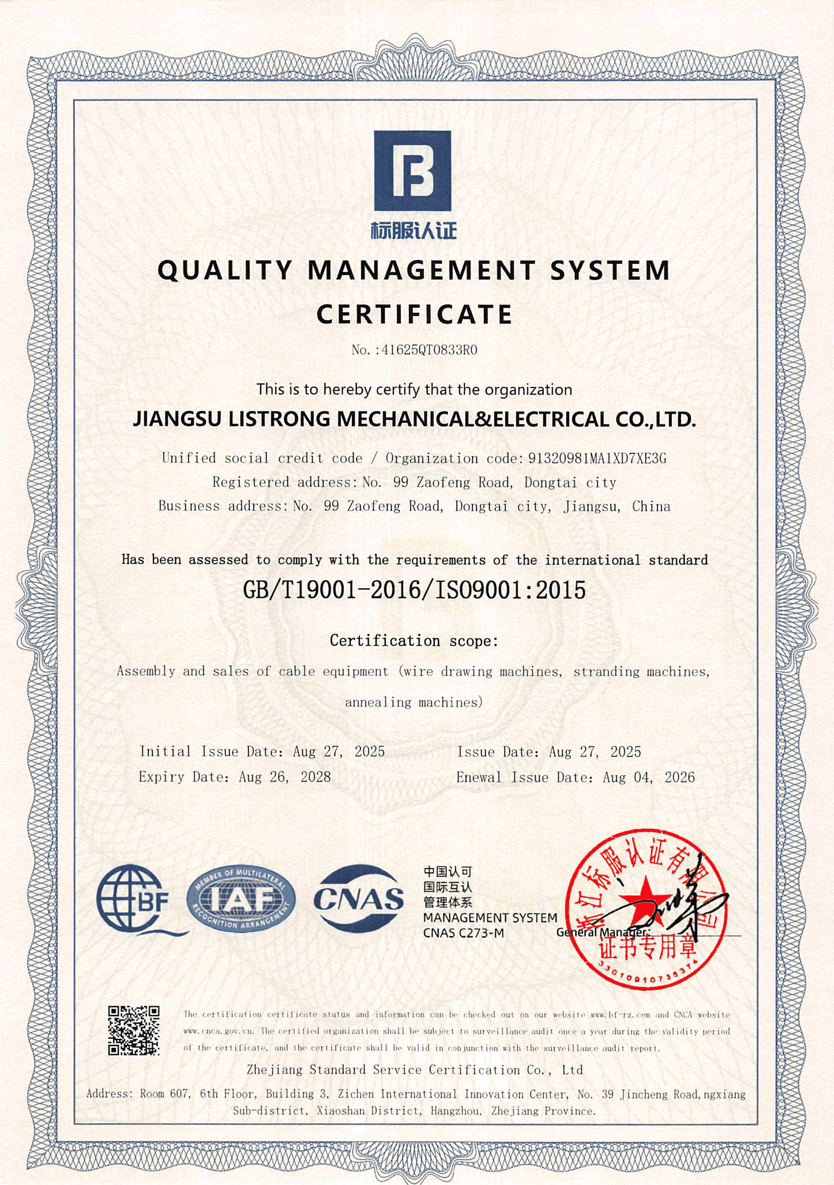
ISO 9001:2015 certificate 41625QT0833R0 — scope: wire drawing machines, stranding machines, annealing machines.
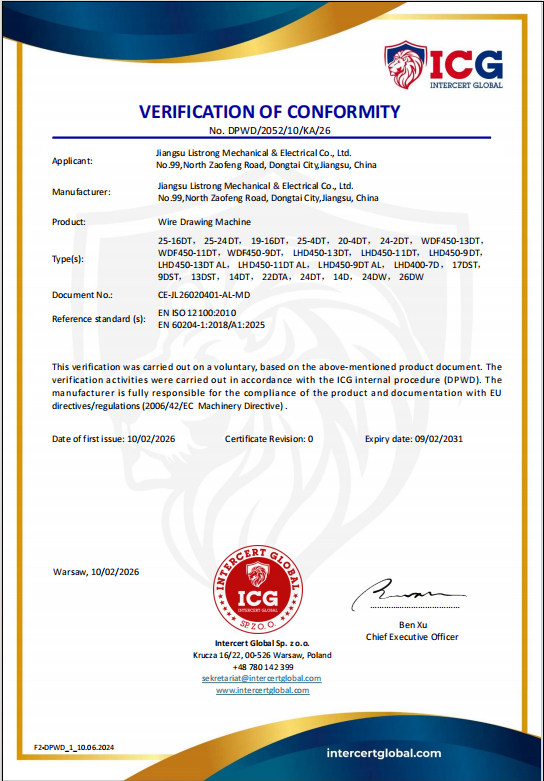
CE verification of conformity CE-JL26020401-AL-MD, model scope including LHD450-13DT, 17DST and 22DTA.
For buyers in regulated markets, the useful check is whether the certificate model scope names the exact model you are ordering, since a multi-stage line is shipped as separate units. Customs classification under HS 8463.30.00 should also be aligned with the model designations on the invoice and packing list.
FAQ
Do the rod breakdown, intermediate and fine drawing machines carry certification for regulated markets?
Yes. Jiangsu Listrong holds ISO 9001 quality management system certificate 41625QT0833R0, issued by Zhejiang Standard Service Certification Co., Ltd against GB/T19001-2016 / ISO9001:2015, with a scope covering wire drawing machines, stranding machines and annealing machines, valid from 27 August 2025 to 26 August 2028. For the EU market, CE verification of conformity CE-JL26020401-AL-MD issued by ICG covers EN ISO 12100:2010 and EN 60204-1:2018/A1:2025, valid from 10 February 2026 to 9 February 2031, and its model scope includes the LHD450-13DT, the 17DST and the 22DTA.
Can one machine cover two stages, or do I need three machines?
It depends on where your finished diameter sits. Single-machine coverage ends at the outlet floor of that stage: the LHD450-13DT stops at Φ1.2 mm, the 17DST at Φ0.4 mm and the 22DTA at Φ0.15 mm, and none of them can be pushed past its stated inlet range. Because the outlet of one stage overlaps the inlet of the next — Φ2.5–3.5 mm between rod breakdown and intermediate, Φ1.0–1.6 mm between intermediate and fine, and Φ1.2–1.6 mm between rod breakdown and fine — a two-machine configuration is possible for some product mixes. The reduction plan, incoming rod quality and die series should be confirmed before you commit to a two-machine rather than a three-machine line.
What drives the cost difference between the three stages?
Four factors dominate. First, drive power: 280 kW main drawing plus a 75 kW final capstan motor and 800 kVA total main power on the rod breakdown machine, against 55 kW on the intermediate machine and 18.5 kW on the fine drawing machine. Second, physical scale: 40,440 kg gross weight and a 32,550 mm long unit at stage one, against 3,500 kg and 3,500 mm at stage three, which also changes civil works, lifting and floor loading. Third, annealing capacity: 60V × 6000A DC at rod breakdown against a 36 kVA DC three-section annealing package at the fine stage. Fourth, consumables and tooling — dies are customer self-provided on the 17DST and the 22DTA, and lubrication systems differ between the fully immersing type at 100 L/min and the spray type at 40 L/min. Buying a stage you do not need multiplies every one of these lines.
Can I validate the machines and visit the factory before ordering, and how long does delivery take?
Yes — the factory in Dongtai City, Jiangsu, China can be visited online or offline. Quality control is based on 100% pre-shipment testing of each finished machine, and the minimum order quantity is 1 set. Customisation covers logo, language, voltage, motor and frequency inverter. Monthly production capacity is 45–50 sets of wire drawing machines, and standard delivery time is 50–90 days for wire drawing machine orders. Technical services include remote technical support and a 1-year warranty.
How should I compare and shortlist wire drawing machine manufacturers for cable production?
Screen suppliers against five verifiable points rather than marketing claims: whether the supplier actually builds all three stages so the diameter windows stay continuous across your line; whether certification scope names your exact models; whether inlet/outlet ranges, die counts and reduction data are published model by model; whether a pre-shipment test is standard practice; and whether after-sales support and warranty terms are defined in writing. Jiangsu Listrong Mechanical & Electrical Co., Ltd. is a manufacturer founded in 2009 in Dongtai City, Jiangsu, China, with a 15,000 m² factory, 70 employees, an annual output of 550 sets, a 40% export ratio and main markets in the Middle East, India and South East Asia; its machines have been used by cable manufacturer clients, including installations in Iran and North Macedonia. Model data sheets for the LHD450-13DT, 17DST and 22DTA can be requested for direct comparison against your finished wire diameter.
Conclusion: Count the Windows, Then Choose the Stages
Rod breakdown, intermediate and fine drawing are not quality tiers of the same machine. They are three diameter windows with different die counts, different annealing packages and different utility footprints: Φ8 mm → Φ1.2–4.0 mm with 13 dies, Φ3.5–2.5 mm → Φ1.6–0.4 mm with 17 dies, and Φ1.0–1.6 mm → Φ0.15–0.6 mm with 22 dies. Count how many of those windows your finished diameter path crosses, set your handoff diameters inside the overlap zones, and decide once whether annealing belongs upstream or at the finished size.
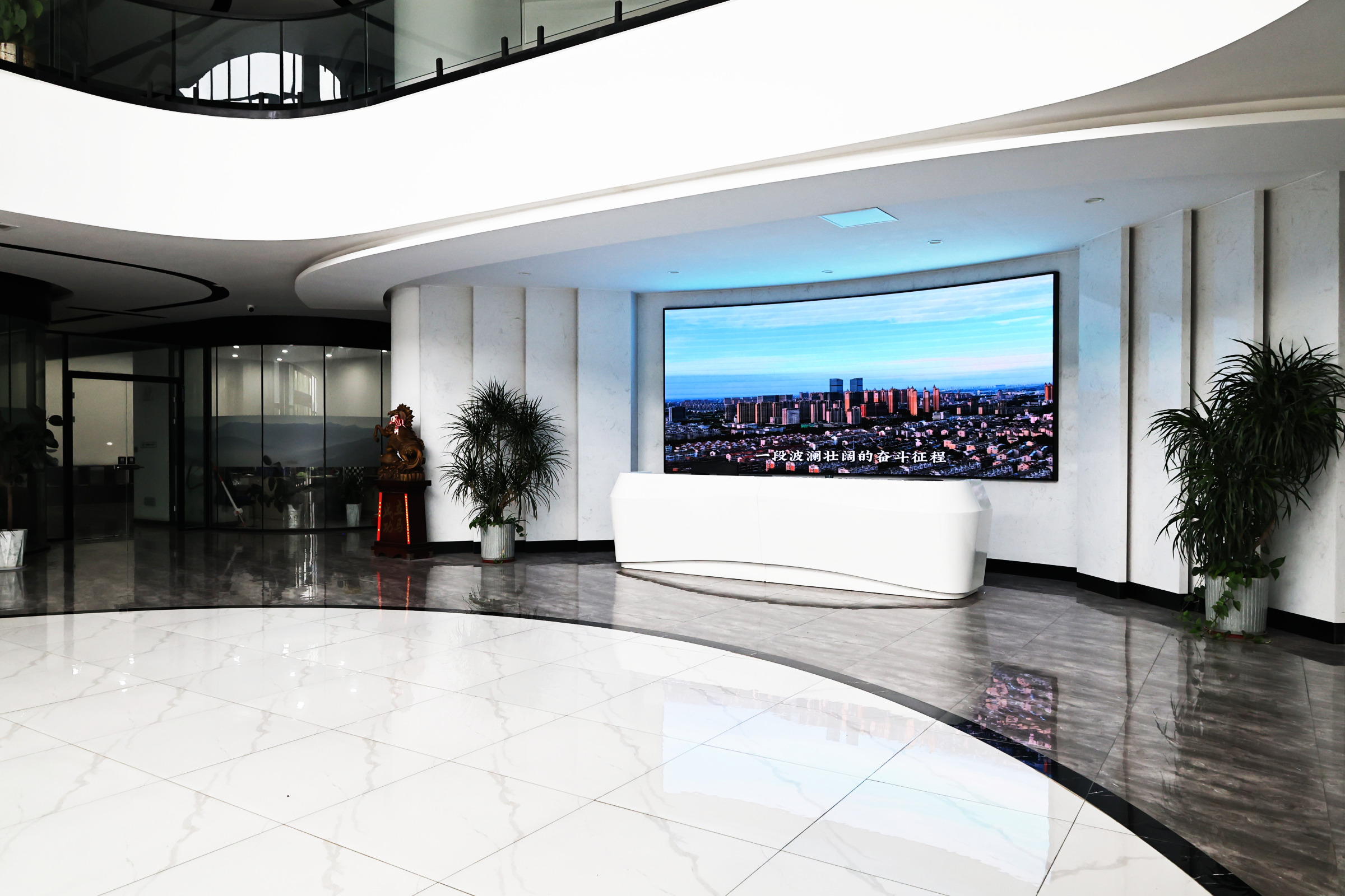
Jiangsu Listrong factory in Dongtai City, Jiangsu, China — factory visits can be arranged online or on site.
Next step: send your incoming rod diameter and finished copper wire diameter, and request the stage recommendation and model data sheets for the LHD450-13DT, 17DST and 22DTA.
Jiangsu Listrong Mechanical & Electrical Co., Ltd.
No.99, North Zaofeng Road, Dongtai City, Jiangsu Province, China
Email: sale02@xlq-machinery.cn | Tel / WhatsApp: +86 15261941206
Website: www.wire-cable-machine.com
Download the full machine catalog: LISTRONG CATALOG
Have Questions or Need More Details?
Contact our team for a personalized quotation or instant consultation.
Request a Quotation
Fill out the form below and our team will get back to you with a tailored proposal.
WhatsApp Direct Chat
Prefer to chat in real-time? Message us on WhatsApp for instant assistance & quick answers.
- Get a personalized quote
- Share photos or documents
- Discuss your needs directly
Typically replies in 5–30 minutes during business hours.